- 您现在的位置:买卖IC网 > Sheet目录321 > DLP-2232H-PSOC5 (DLP Design Inc)MODULE PSOC5 USB ADAPTER FT2232H
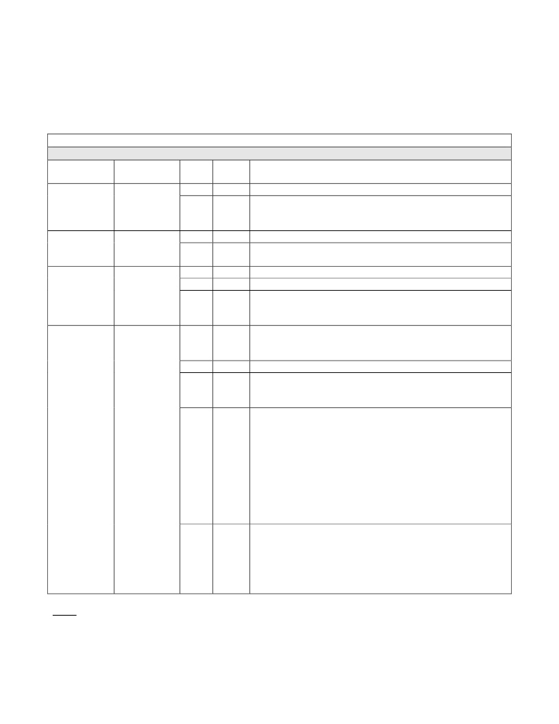
If you are using the VCP drivers, begin by opening the COM port, and send multi-byte commands as
shown in Table 1 below. There is no need to set the baud rate because the DLP-2232H-PSOC5 uses
a parallel interface between the USB IC and the PSoC ? 5. (The Ping Command can be used to locate
the correct COM port used for communicating with the DLP-2232H-PSOC5, or you can look in Device
Manager to see which port was assigned by Windows.) If you are using the D2XX drivers as with the
Test Application, no COM port selection is necessary.
TABLE 1
Command Packets
Command
Hex
Packet
Description
Byte
Value
Return/Comments
Ping
Issues Ping
0
1
0x02 Packet Byte Count
0x27 Ping Command - 0x50 1 (ASCII ‘P’) will be returned
indicating that the DLP-2232H-PSOC5 is found on the
selected port.
Flash
Flashes
LED
0
1
0x02 Packet Byte Count
0x28 Flashes LED command; lasts approximately one
second. Returns echo of command sent (0x28) 1 only.
LED On/Off
Accesses
the Internal
0
1
0x03 Packet Byte Count
0x29 Control LED Command
Version/
Status
Registers
2
0x00
or
0x01
LED State: 0x00 = LED Off; 0x01 = LED On
Returns echo of command sent (0x29) 1 only.
Read/Write
Pin
Reads the
State or
0
0x04
or
Packet Byte Count: 4 Bytes required for Read, 5 bytes
required for Write.
Writes to
0x05
One of the
1
0x30 Read/Write Pin Command
User I/O
Pins
2
0x00
–
User I/O channel/port pin numbers (these are described
in Table 2).
0xF7 4
3
4 5
0x00
or
0x01
0x00
or
0x01
Selects Write or Read as follows:
0x00 = Write Pin (Specified Pin is an Output)
0x01 = Read Pin (Specified Pin is an Input)
User I/O pin 0xnn is read and returns 1 the first byte as:
0x00 = User I/O Pin 0xnn is Low
0x01 = User I/O Pin 0xnn is High
Read Pin returns echo of command sent (0x30) 1,2 as
the second byte.
Write Value:
0x00 = User I/O Pin 0xnn is Low
0x01 = User I/O Pin 0xnn is High
Write Pin returns echo of command sent (0x30) 1,2 only.
Notes :
1. If the value 0xE0 is returned the module received an invalid command byte (not 0x27,0x28,0x29 or 0x30).
2. If the value 0xE1 is returned the module received an invalid port pin byte (refer to table 2 for valid ports).
3. If the value 0xE3 is returned the module received a read request for a write only port pin (P15.6 & P15.7).
4. Not all Hex values between 0x00 and 0xF7 are valid (refer to Table 2 for valid channel values).
5. Byte 4 is only needed when Byte 3 is set to 0 (Write).
Rev. 1.0 (February 2012)
9
? DLP Design, Inc.
发布紧急采购,3分钟左右您将得到回复。
相关PDF资料
DM163014
BOARD DEMO PICDEM4 12F629,16F630
DM163022-1
BOARD DEMO PIC16F87X PIC18FXX2
DM163030
KIT DEV PICDEM LCD2
DM163035
KIT DEVELOPMENT PICDEM LAB
DM164120-1
BOARD DEMO PICKIT 2 LP COUNT
DM164120-3
BOARD DEMO PICKIT2 28-PIN
DM164120-5
BOARD DEMO PICKIT 2 64/80-PIN
DM164123
KIT MANAGEMENT SYSTEM PICDEM
相关代理商/技术参数
DLP-2232H-SF
功能描述:界面模块 USB Micrcontroller FPGA Module
RoHS:否 制造商:4D Systems 产品:Serial Converters 通道/端口数量: 数据速率: 接口类型:USB, UART 工作电源电压:3.3 V, 5 V 最大工作温度:
DLP-2232M
功能描述:界面模块 Multi-Mode UART/FIFO
RoHS:否 制造商:4D Systems 产品:Serial Converters 通道/端口数量: 数据速率: 接口类型:USB, UART 工作电源电压:3.3 V, 5 V 最大工作温度:
DLP-2232M-G
功能描述:界面模块 Multi-Mode UART/FIFO
RoHS:否 制造商:4D Systems 产品:Serial Converters 通道/端口数量: 数据速率: 接口类型:USB, UART 工作电源电压:3.3 V, 5 V 最大工作温度:
DLP-2232ML
功能描述:界面模块 Low Profile 2232M
RoHS:否 制造商:4D Systems 产品:Serial Converters 通道/端口数量: 数据速率: 接口类型:USB, UART 工作电源电压:3.3 V, 5 V 最大工作温度:
DLP-2232ML-G
功能描述:MODULE USB ADAPTR FOR FT2232D LP RoHS:是 类别:编程器,开发系统 >> 评估演示板和套件 系列:- 标准包装:1 系列:- 主要目的:数字电位器 嵌入式:- 已用 IC / 零件:AD5258 主要属性:- 次要属性:- 已供物品:板 相关产品:AD5258BRMZ1-ND - IC POT DGTL I2C1K 64P 10MSOPAD5258BRMZ10-ND - IC POT DGTL I2C 10K 64P 10MSOPAD5258BRMZ100-ND - IC POT DGTL I2C 100K 64P 10MSOPAD5258BRMZ50-ND - IC POT DGTL I2C 50K 64P 10MSOPAD5258BRMZ1-R7-ND - IC POT DGTL I2C 1K 64P 10MSOPAD5258BRMZ10-R7-ND - IC POT DGTL I2C 10K 64P 10MSOPAD5258BRMZ50-R7-ND - IC POT DGTL I2C 50K 64P 10MSOPAD5258BRMZ100-R7-ND - IC POT DGTL I2C 100K 64P 10MSOP
DLP2232ML-G
功能描述:界面模块 Low Profile 2232M
RoHS:否 制造商:4D Systems 产品:Serial Converters 通道/端口数量: 数据速率: 接口类型:USB, UART 工作电源电压:3.3 V, 5 V 最大工作温度:
DLP-2232MSP
功能描述:界面模块 USB to MSP430 w/ FTDI FT2232H
RoHS:否 制造商:4D Systems 产品:Serial Converters 通道/端口数量: 数据速率: 接口类型:USB, UART 工作电源电压:3.3 V, 5 V 最大工作温度:
DLP-2232MSPF
功能描述:界面模块 MICROCNTRLLR MOD USB
RoHS:否 制造商:4D Systems 产品:Serial Converters 通道/端口数量: 数据速率: 接口类型:USB, UART 工作电源电压:3.3 V, 5 V 最大工作温度:
